
The best splice is the one you never make. NASA-STD-8739.4A puts it plainly: the simplest, most reliable wiring is one continuous, unbroken conductor from point to point.1 The FAA's advice is shorter: keep splicing to a minimum.2 But sometimes splice happens (see what I did there) harnesses get repaired, wires get extended, or a small wire has to grow to fit a large contact barrel or any other reason you may not have a choice. Some of those are among the cases where a splice is specifically allowed.3
So when you do splice, you're making two decisions. The first is which kind of splice will meet your requirements. The second is whether the conductor going into it is the right size for it, and that comes down to circular mil area (CMA). Splicing is one of the easiest design concepts to mess up.
The five kinds of splice
On aerospace and military harnesses you'll run into five main types. When dealing with purely commercial harness designs there are many more options. For the purposes of our conversation we are going to stay in the mil/aero design space:
- the butt splice: a crimp barrel in a sealed heat-shrink sleeve with or without hot melt adhesive at the ends, these come in mil-spec and commercial varity;
- the solder sleeve: also mil-spec or commercial, with or without a pick-off lead. A pick-off lead is an extra wire that comes pre-installed in the solder sleeve. These same components are also used for twisted shield pair shield terminations;
- the parallel crimp splice: a commercial part with the wires side by side in one barrel;
- the shield splice: carries a cable's shield across a splice in its conductors, same as a solder sleeve;
- the hand-soldered splice: lap, lash or Western Union, made at the bench by hand using solder.
Butt splice: crimped, then sealed
SAE AS81824 covers environment-resistant crimp splices: a metal crimp barrel inside a heat-shrink sleeve, with a hot melt adhesive sealing ring at each end (Figure 1). This hot melt is to create an environmental seal around the splice. The wires go in from opposite ends until the conductor ends meet near the center. Each half of the barrel is crimped with the tool and setting for that splice size. Then you heat the sleeve: it shrinks, and the rings melt onto the insulation and seal both ends.
The parts you'll see most are M81824/1-1, M81824/1-2 and M81824/1-3, the three sizes on the AS81824/1 sheet.4 Each size takes its own range of conductor, and that range is what you check your CMA total against.
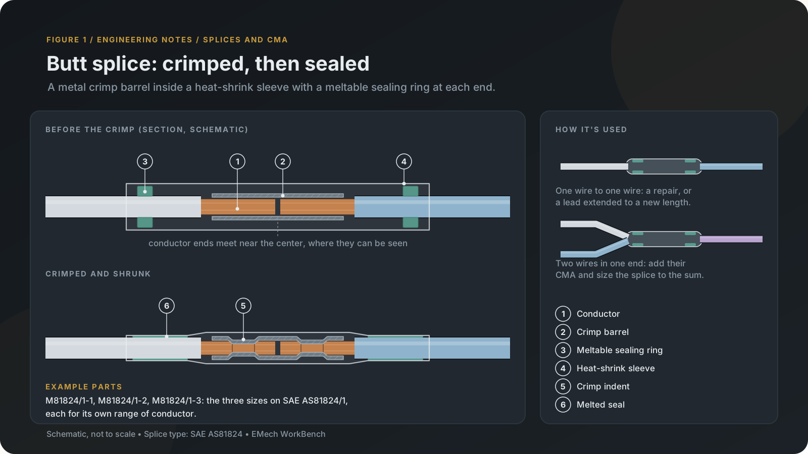
A self-insulated splice is the strongly preferred choice, as an environmentally sealed splice is the reliable way to join conductors in areas exposed to severe wind and moisture, the FAA's SWAMP areas.5 As well the sleeving helps to provide bend and strain releif to the joint itself.
Pluses
- It's a qualified part made to a spec, and it's generally installed with a calibrated ratcheting crimp tool. The crimp itself can be checked with go/no-go gauges or have its depression checked.6 Done right, every one comes out the same and takes minimal training for technicians to install correctly.
- When installed correctly they create a gas tight bond in the crimp area. This can minimize corrosion over time.
- Both ends are sealed by the sleeve and the hot melt adhesive at the ends.
- No solder and no flux. AS81824 splices are made for tin-, silver- and nickel-plated conductors.7
- One end can take two or more wires, as long as their total conductor area fits the barrel.8 There's more on that under Adding it up.
Minuses
- It's the biggest and heaviest of the sealed splices. Solder-style splices are smaller and lighter.9
- Each splice size needs its own tool setting, and the wrong one makes a bad crimp that can look fine from the outside.
- The barrel and sleeve make a stiff section, so it has to stay out of places where the harness flexes.10
- It's permanent. Fixing a bad one means cutting it out, and that uses up wire length.
- Like all splices if their locations are not staggered down the length of the harness they can create a bulge in the harness bundle diameter. If there are enought splices in a harness this could inhibit its installation.
Solder sleeve: solder, insulation and seal in one heat
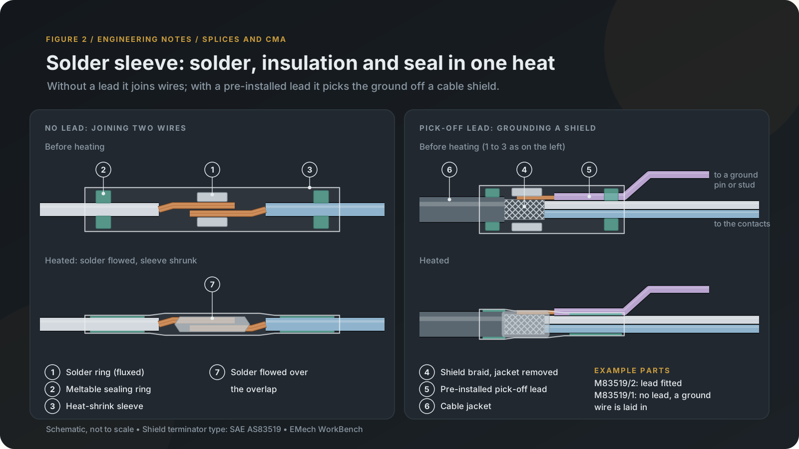
A solder sleeve is a heat-shrink sleeve with a ring of fluxed solder in the middle and a meltable sealing ring at each end (Figure 2). One heating does everything: the solder melts and flows over the conductors, the sleeve shrinks, and the rings seal onto the insulation.
Without a lead, the sleeve joins wires. The stripped conductors lie side by side under the solder ring. Solder-style splices are mainly meant for one conductor to one conductor, but they can take more if the splice is sized for all of them.9
With a lead, the sleeve picks the ground off a cable shield. You strip a band of the jacket, slide the sleeve over the exposed braid and heat it. The lead is soldered to the braid without cutting the shield, and it runs on to a ground pin in the connector, a ground stud, or the banding porch of a backshell. That lead is the pick-off. When several shields are grounded together, keep it to no more than four conductors plus a drain wire in one splice.11 The Mill-Spec component comes with a red ink over the solder rind, when the splice is heated properly this red ink will disappear. This eleminates the need for in-process inspections of a solder joint.
The mil-spec part is SAE AS83519, and it's written as a shield termination.12 Its /1 sheet (M83519/1-1 to /1-5) has no lead, so a ground wire is laid in against the braid before heating;13 its /2 sheet (for example M83519/2-1) comes with the lead (pick off wire) already installed. This is helpful when daisy chaining shields or creating a one to two splice.
Pluses
- It's the smallest and lightest sealed splice.9
- One heating solders, insulates and seals.
- No calibrated crimp tools needed.
- You can see the joint through the sleeve. A good one has a fully wetted solder ring whose outline is gone, a sleeve that follows the wires, and sealing rings tight on the insulation.14
- With a lead, it can make installtion easier.
Minuses
- Heat. Nearby wires, parts and solder joints have to be protected while it's heated,15 and the heat tool has to be properly set to give the heat the sleeve's maker calls for.16
- Because of he the emedded flux. Heat-shrinkable soldering devices have to stay away from sensors and optics that surface contamination would harm.17 This is less of a concern for splices placed far away from other devices.
- The solder and flux have to suit the wire's plating.18 Nickel-plated conductors, for one, need different solder sleeves or flux from tin- or silver-plated ones.19
- An under-heated sleeve can look finished from the outside. This is why it is prefered to use the Mil-Spec compoenet that have the red ink to ensure the solder was fully melted.
- The solder makes a short, stiff spot in the wire.
- Solder joints are more susceptible to breakage in areas that bend.
- If not sized properly there might not be enough solder in the sleeve and the solder can't reach every strand.
- Wire must be selected to survive the heat applied during the installtion procedure.
Parallel crimp splice: one barrel, wires side by side
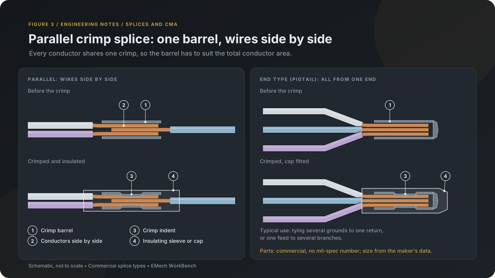
A parallel crimp splice is a plain metal barrel. In this authors opinion, this is the strongest mechanical connection. Because all the conductors are overlaped they create a cross section that is larger than any other conductor in the same path. If the wire gauges are large enough you can literally hang by one of these splices. The wires lie on top of one another in it, not end to end, and one crimp holds them all (Figure 3).
In the end type, or pigtail, every wire comes in from the same end and the closed end is capped. NASA's standard covers both forms as crimp ferrule splices: the barrel is sized from the maker's data, and they're usually crimped with a two-indenter tool instead of the usual four.20
For both applications, this splice type is not electrically isolated in any way. To properly use a splice like this, the designer has to include heat shrink or some other covering in the design to isolate the connection. The recomendation is to use adhesive lined heat shrink in high reliability applications.
There's no mil-spec number to quote for these. They're commercial parts, and their part number and wire range are determined by the manufacture. However these components are used widely over military and aerospace equipment.
Pluses
- It's an easy way to join several wires at one point, like tying grounds to one return or feeding several branches.
- It allows the joining of wire with a large difference in wire gauge.
- It's good for a one to many connection
- It's short, and one crimp does every wire.
- The parts are cheap and easy to find.
Minuses
- No mil-spec stands behind it. The barrel size comes from the manufactures data, and the design requirement have to allow commercial parts.
- It isn't insulated or sealed on its own: it needs a sleeve or a cap.
- With the end type, every wire leaves in the same direction, so the bundle has to double back.
- The two-indenter tool is one more tool to buy, verify and control.
- Every conductor shares one barrel, so this is where the total conductor area matters most.
Shield splice: join the wires, then the shield
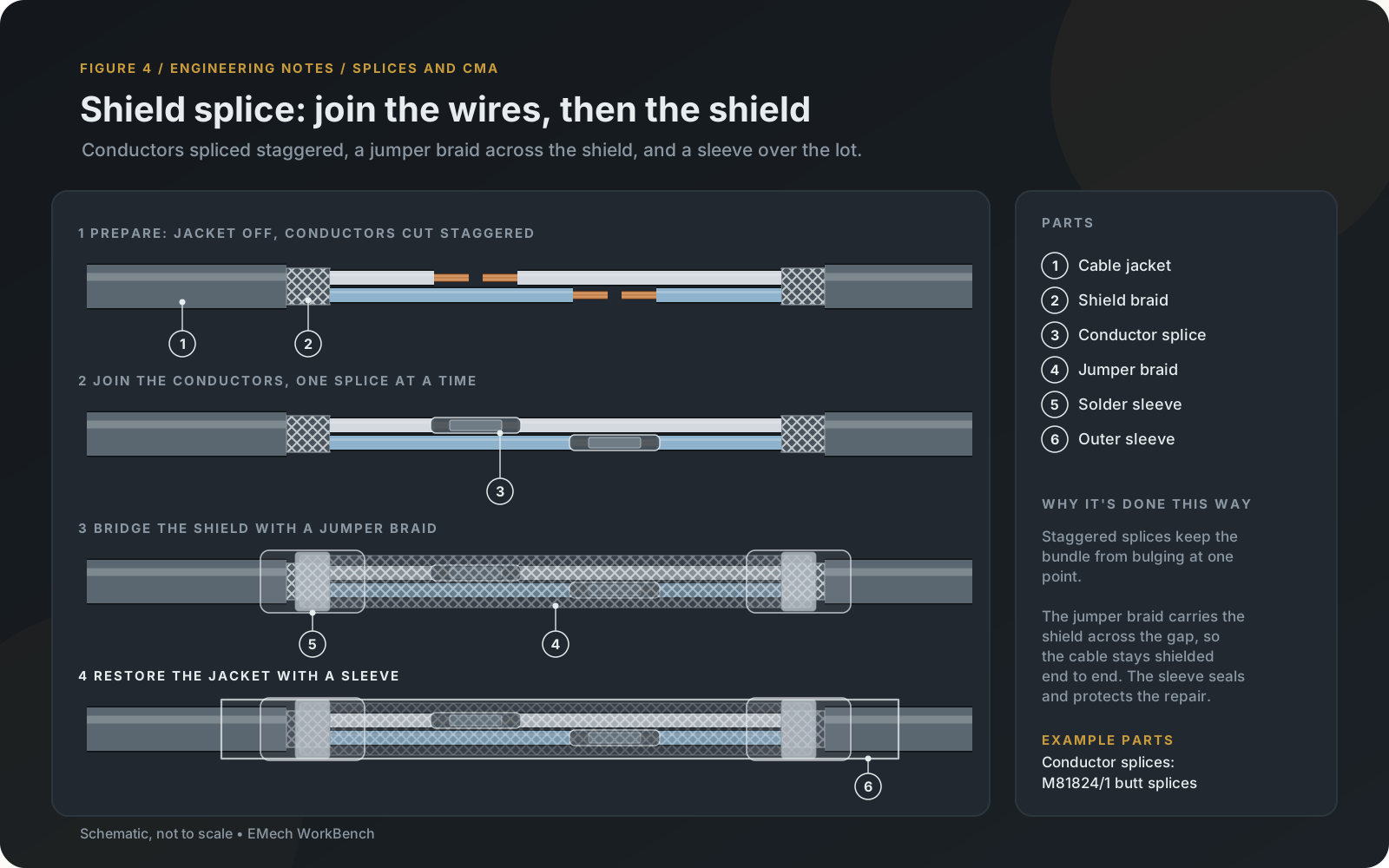
Splicing a shielded cable means splicing two things: the conductors, and the shield around them (Figure 4). These are used in applications where a conductor in a twisted shielded set need to be spliced. This is probably the least preferred of all the splice options. First, remove the jacket and cut the conductors at staggered points. Next, join each conductor with its own butt splice, such as an M81824/1, offset along the cable so the splices don't sit side by side. Then lay a jumper braid across the gap between the two cut shields and bond it to each one with a solder sleeve. Finally, an outer heat-shrink sleeve covers the whole repair, from jacket to jacket.
Not only is this a sub-par solution for maintaining shielding across a shielded set. It is also difficult to install, the shielding is sub-par, and introduces many opportunities for failure. However there are cases where this is the only option. Splices like this should only be installed in sections of a harness that have no bends and is not required to flex.
Pluses
- The shield stays continuous, so the cable keeps its EMI protection through the repair.
- You can repair a damaged length without replacing the whole cable.
Minuses
- It's the longest and bulkiest splice, and it has to be staggered to keep the bundle from bulging.
- There are several steps and several heat cycles, so there's more to inspect.
- The shield path is only as good as the two solder-sleeve joints on the braid.
- Splicing coax and multiplex data bus cable needs approved data.21 A splice in those cables changes more than the wiring diagram shows.
- Wire must be selected to survive the heat applied during the installtion procedure.
Hand-soldered splice: lap, lash and Western Union
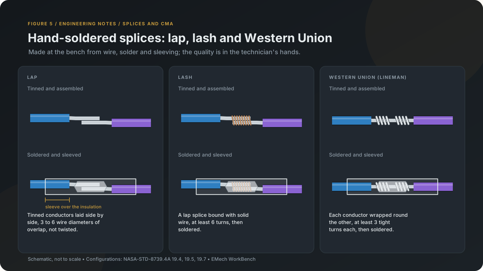
A hand-soldered splice needs nothing but wire, solder and sleeving, so there's no part number to call out. This is the oldest form of a wire splice making it the most well tested and the one with the most room for improvment, NASA's standard gives three forms (Figure 5):
- In a lap splice, tinned conductors lie side by side with 3 to 6 wire diameters of overlap, not twisted together.22
- A lash splice is a lap splice bound with solid wire, at least 6 turns, then soldered.23
- In a Western Union (lineman) splice, each conductor is wrapped around the other at least 3 tight turns, then soldered.24
The sleeving has to cover the splice and run onto the insulation by at least twice the diameter of the largest wire.25 When creating this kind of splice it is strongly recommended to use adhesive lined heat shrink to make the area as rigid as possible. Bending and strain is the enemy of hand soldered splices. However a properly done solder splice can be mechanically stronger than than the conductors themselves.
Pluses
- It needs no special parts or crimp tooling, so it works for any combination of wires.
- A lap splice is small and makes the smallest impact to bundle diameter.
- A Western Union splice holds together mechanically even before it's soldered.
Minuses
- The quality is entirely in the technician's hands.
- Hand done solder joint normally require certified technicins and in process inspections.
- Solder wicks up the strands and leaves a stiff section. The wire flexes at the end of that section, and that's where it breaks.
- The iron's heat can reach the insulation. The wire must be selected to survive the heat.
- It has to be cleaned and inspected before it's sleeved, and the joint has to meet the solder-quality requirements.26
- It's slow, and a Western Union splice is bulky too.
Side by side
| Splice | Joined by | Sealed | Size | Tools | Spec or example parts |
|---|---|---|---|---|---|
| Butt splice | Crimp | Yes | Largest of the sealed splices | Crimp tool and the setting for each size | SAE AS81824 (M81824/1-1 to /1-3) |
| Solder sleeve | Solder, one heating | Yes | Smallest | Heat tool | SAE AS83519 (/1 no lead, /2 with lead) |
| Parallel crimp splice | One crimp, all wires | No | Short | Crimp tool, often two-indenter | Commercial: maker's data |
| Shield splice | Crimp, plus solder sleeves on the braid | Yes | Longest | Crimp tool and heat tool | Built from the splices above |
| Hand-soldered | Solder | Only with sleeving | Small (lap) to bulky (Western Union) | Iron and solder | NASA-STD-8739.4A forms |
Circular mil area
Wire gauge is a label, and labels don't add up: two 22 AWG wires are not a 20 AWG wire. What adds up is conductor area, and wiring measures it in circular mils.
One circular mil (CM) is the area of a circle 1 mil, one thousandths of an inch (0.001 in) across. Measured that way, the area of any round conductor is simply its diameter in mils, squared:
CMA = d², with d in mils (one thousandths of an inch).
There's no π to carry around, which is the whole point of the unit. If you need ordinary units, 1 CM is 0.7854 square mil, or 0.000507 mm².
A stranded conductor isn't one circle. It's a bundle of small ones with gaps between them, so you measure the strands, not the outside of the bundle:
CMA = number of strands × (strand diameter in mils)²
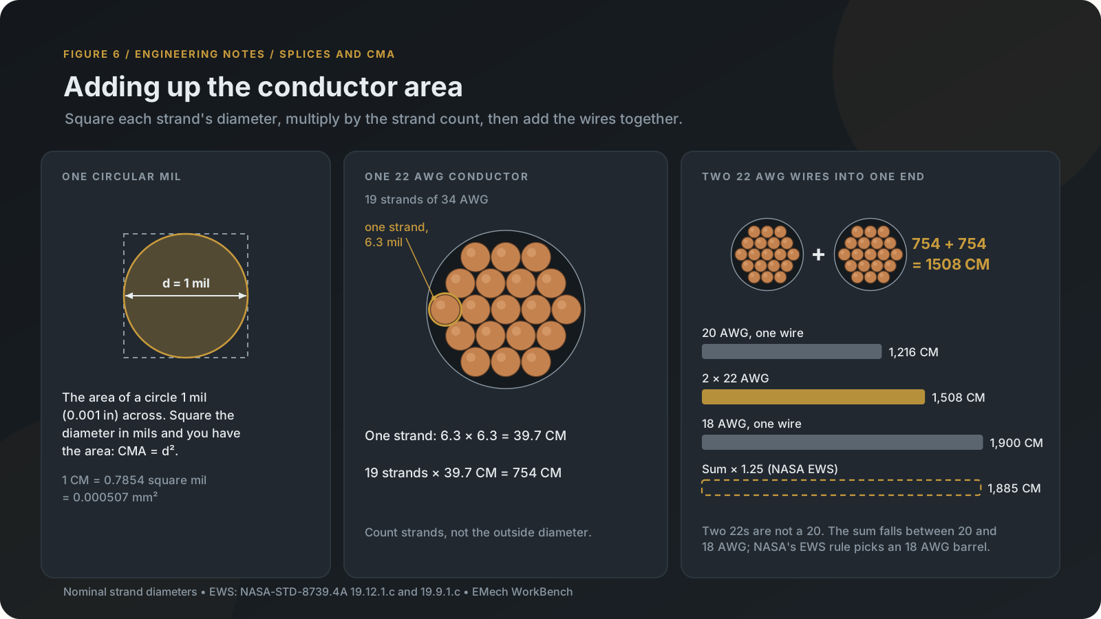
Take aerospace 22 AWG wire, which is usually 19 strands of 34 AWG. A 34 AWG strand is 6.3 mil across, so each strand is 6.3² = 39.7 CM, and the wire is 19 × 39.7 = 754 CM (Figure 6). Solid 22 AWG wire is about 642 CM,27 so a stranded "22 AWG" isn't the same area as a solid one. Stranded gauges are nominal sizes.
Adding it up
- For each wire going into the splice, find its stranding (strand count and strand gauge) on the wire's spec sheet.
- Square the strand diameter in mils and multiply by the strand count. That's the wire's CMA.
- Add up the wires that share a barrel. In a butt splice each end is its own barrel, so total each end separately. In a parallel splice, every wire shares the one barrel.
- Compare the total with the barrel's range on the splice's spec sheet or the maker's data.
NASA's standard adds a margin on top. It multiplies the sum of the CMAs by 1.25 and calls the result the equivalent wire size, or EWS.8 The barrel is then sized to the EWS, or to the next larger size if the EWS falls between sizes.28
Here's the same arithmetic for the usual aerospace strandings, the 19- and 37-strand constructions the SAE AS22759 wire sheets use. The strand diameters are the nominal AWG sizes, rounded to 0.1 mil the way wire tables print them.27
| Wire size (AWG) | Stranding | Strand diameter (mil) | CMA |
|---|---|---|---|
| 26 | 19 × 38 AWG | 4.0 | 304 |
| 24 | 19 × 36 AWG | 5.0 | 475 |
| 22 | 19 × 34 AWG | 6.3 | 754 |
| 20 | 19 × 32 AWG | 8.0 | 1,216 |
| 18 | 19 × 30 AWG | 10.0 | 1,900 |
| 16 | 19 × 29 AWG | 11.3 | 2,426 |
| 14 | 19 × 27 AWG | 14.2 | 3,831 |
| 12 | 37 × 28 AWG | 12.6 | 5,874 |
| 10 | 37 × 26 AWG | 15.9 | 9,354 |
Two worked examples:
- Two 22 AWG wires into one end: 754 + 754 = 1,508 CM. That's more than a 20 AWG wire (1,216) and less than an 18 (1,900). The EWS is 1,508 × 1.25 = 1,885 CM, so the rule gives you an 18 AWG barrel.
- A 20 AWG and a 22 AWG into one end: 1,216 + 754 = 1,970 CM, already more than a single 18 AWG wire. The EWS is 1,970 × 1.25 = 2,463 CM. That's just over 16 AWG (2,426), so the rule goes up to the next size, 14 AWG.
Either way, the end with fewer wires has to fit the same barrel. A barrel sized for the crowded end can be too big for a single wire on the other end, so check both ends against the range.
Why the total matters: too little or too much
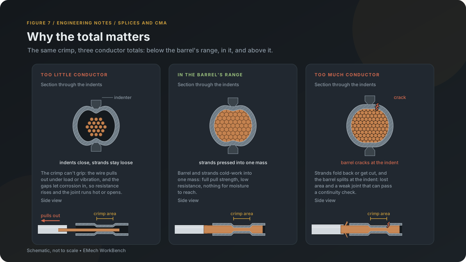
A crimp works by squeezing the barrel and the strands together at the indents until they cold-work into one solid mass, with no gaps for air or moisture to get into. That only happens when the amount of conductor matches the barrel (Figure 7).
Too little conductor
- The crimp can't grip, and likely to allow the conductor to be pulled out. A crimp that isn't tight enough may not hold the wire, and it's open to high resistance from corrosion between the barrel and the wire.6
- The wire can pull out under load or vibration, sometimes long after it passed inspection.
- The gaps let corrosion in, resistance climbs, and the joint runs hot or goes intermittent.
- In a solder sleeve, too small a bundle leaves the sealing rings loose on the insulation, and the seal is gone.
Too much conductor
- The wires won't go all the way into the barrel, so the conductor ends can't be seen where they should be.29 Or strands get folded back outside the barrel to make them fit. This would effectivly makes the splice a fuse waiting to blow.
- The crimp cuts strands or cracks the barrel. Every cut strand is area lost, and a cracked barrel is a weak joint.
- In a solder sleeve, the solder can't flow through to the middle of an oversized bundle.
Both failures can pass a continuity check on the bench. The arithmetic takes a minute, and the failure can take years to show up.
Before you splice
Wherever the splice goes, a few rules apply:
- Stagger splices in a bundle so the bundle doesn't bulge at one point.30
- Keep splices out of places where the harness flexes, and out of bends.10
- Keep splices at least 12 inches from a termination device. The exceptions are splicing several wires to one wire, and adapting a wire to fit a contact's crimp barrel.31
- Keep splices at least two harness diameters from a breakout.32 This avoids places a splice inside an area that may bend.
- Make no more than one splice in a wire between any two disconnect points, apart from the listed exceptions.3
- Show each splice's type and location on the drawing.33 For a splice with more than one wire in an end, put the CMA total next to it, so whoever builds or inspects it can check the math.
References
- NASA-STD-8739.4A with Change 1 (2016), Workmanship Standard for Crimping, Interconnecting Cables, Harnesses, and Wiring, paragraph 7.2.32, p.24. ↩︎
- FAA Advisory Circular AC 43.13-1B with Change 1, Acceptable Methods, Techniques, and Practices: Aircraft Inspection and Repair, paragraph 11-167a, p.11-65. ↩︎
- AC 43.13-1B, paragraph 11-167c, p.11-65. ↩︎
- DLA Qualified Products Database (QPD), QPL-81824 part listing for M81824/1, checked 2026-10-25. ↩︎
- AC 43.13-1B, paragraph 11-167b, p.11-65. ↩︎
- AC 43.13-1B, paragraph 11-178, pp.11-69 and 11-70. ↩︎
- SAE AS81824, Splices, Electric, Permanent, Crimp Style, Copper, Insulated, Environment Resistant: scope. ↩︎
- NASA-STD-8739.4A, paragraph 19.12.1c, p.77. ↩︎
- NASA-STD-8739.4A, paragraph 19.3, p.68. ↩︎
- NASA-STD-8739.4A, paragraph 7.2.36, p.25. ↩︎
- NASA-STD-8739.4A, paragraph 11.3.2, p.46. ↩︎
- QPD, QPL-83519 (SAE AS83519, Shield Termination, Solder Style, Insulated, Heat-Shrinkable, Environment Resistant) part listings for M83519/1 and M83519/2, checked 2026-10-25. ↩︎
- NASA-STD-8739.4A, Figure 11-2, Example of Individual Shield Termination Using a Heat Shrinkable Solder Sleeve. ↩︎
- NASA-STD-8739.4A, paragraph 19.6.1c, pp.70-71. ↩︎
- NASA-STD-8739.4A, paragraph 7.2.41, p.25. ↩︎
- NASA-STD-8739.4A, paragraph 19.6.1b, p.70. ↩︎
- NASA-STD-8739.4A, paragraph 7.2.39, p.25. ↩︎
- NASA-STD-8739.4A, paragraph 7.2.40, p.25. ↩︎
- AC 43.13-1B, paragraph 11-77b(3), p.11-36. ↩︎
- NASA-STD-8739.4A, paragraphs 19.11 and 19.11.1b, with its note, p.75. ↩︎
- AC 43.13-1B, paragraph 11-167, p.11-65. ↩︎
- NASA-STD-8739.4A, paragraph 19.4.1, pp.68-69. ↩︎
- NASA-STD-8739.4A, paragraph 19.5.1, pp.69-70. ↩︎
- NASA-STD-8739.4A, paragraph 19.7.1, p.71. ↩︎
- NASA-STD-8739.4A, paragraph 19.2.6, p.67. ↩︎
- NASA-STD-8739.4A, paragraphs 19.2.2, 19.2.3 and 19.2.4, p.67. ↩︎
- ASTM B258, Standard Specification for Standard Nominal Diameters and Cross-Sectional Areas of AWG Sizes of Solid Round Wires Used as Electrical Conductors. ↩︎
- NASA-STD-8739.4A, paragraph 19.9.1c, p.74. ↩︎
- NASA-STD-8739.4A, paragraph 19.12.1a, p.76. ↩︎
- AC 43.13-1B, paragraph 11-167d, p.11-65; NASA-STD-8739.4A, paragraph 7.2.35, p.25. ↩︎
- AC 43.13-1B, paragraphs 11-167e and 11-167f, p.11-65. ↩︎
- NASA-STD-8739.4A, paragraph 7.2.37, p.25. ↩︎
- NASA-STD-8739.4A, paragraph 7.2.38, p.25. ↩︎