
One concept that designers of electrical harnesses using Mil-Spec hardware learn, either through experience or by handling the hardware, is keyway tolerance. As a purely mechanical designer, your instinct is to call out the tightest tolerance that can be measured. After your first harness fails inspection, you quickly learn there is a limit to how tightly you can hold a keyway location. Not only are angles like that difficult to measure accurately, but the components are limited to a minimum angle. Like all great engineering responses, this is a feature, not a bug. This minimum angle is due to the anti-rotation teeth on the connector and backshell. Once you understand how those teeth set the step, and where the steps start, you know which angles you can actually put on the drawing.
The anti-rotation teeth
Look at the back of any MIL-DTL-38999 connector and you'll see a ring of small teeth around the accessory thread. The backshell has a matching ring. When the coupling nut is tightened, the two rings mesh, and from then on the backshell can only sit at whole-tooth positions.
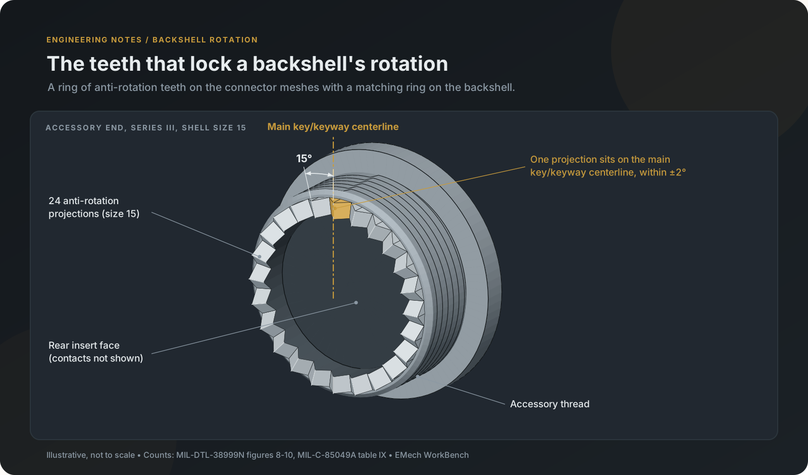
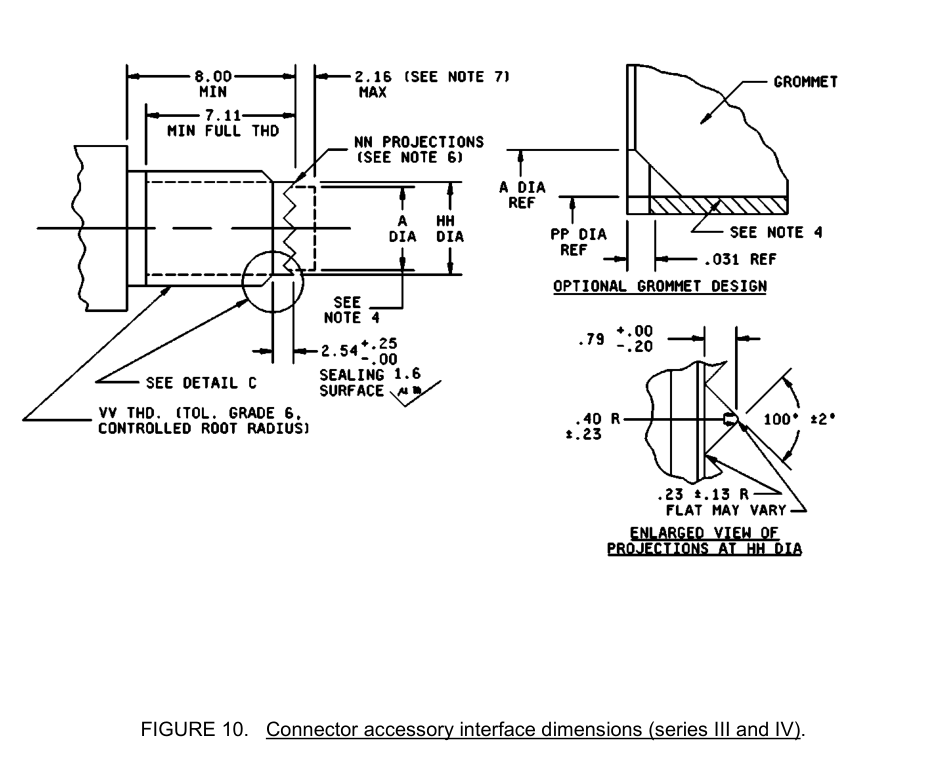
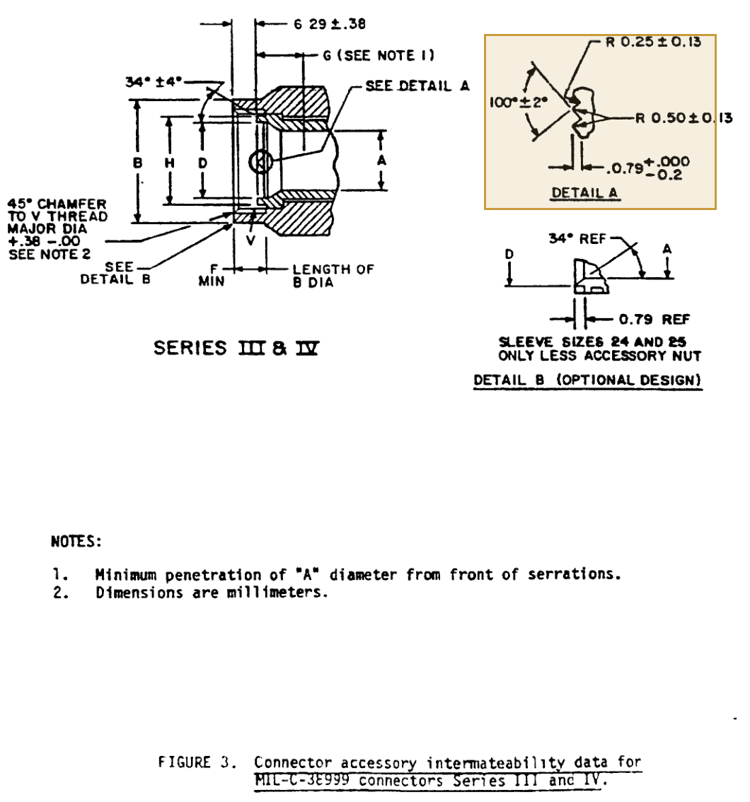
The spec calls them anti-rotation projections. MIL-DTL-38999 gives the count for each shell size in the "NN" column of the connector accessory interface figures: figure 8 for Series I, figure 9 for Series II and figure 10 for Series III and IV (the tables are under the tooth count table below). The accessory side matches it: MIL-C-85049A table IX lists the same counts as "No. of Teeth" for accessories that fit Series III and IV connectors, and its figure 3 shows the serrations. Both sides use a tooth profile with a 100° ±2° included angle (MIL-DTL-38999N figure 10, enlarged view of the projections; MIL-C-85049A figure 3, detail A).
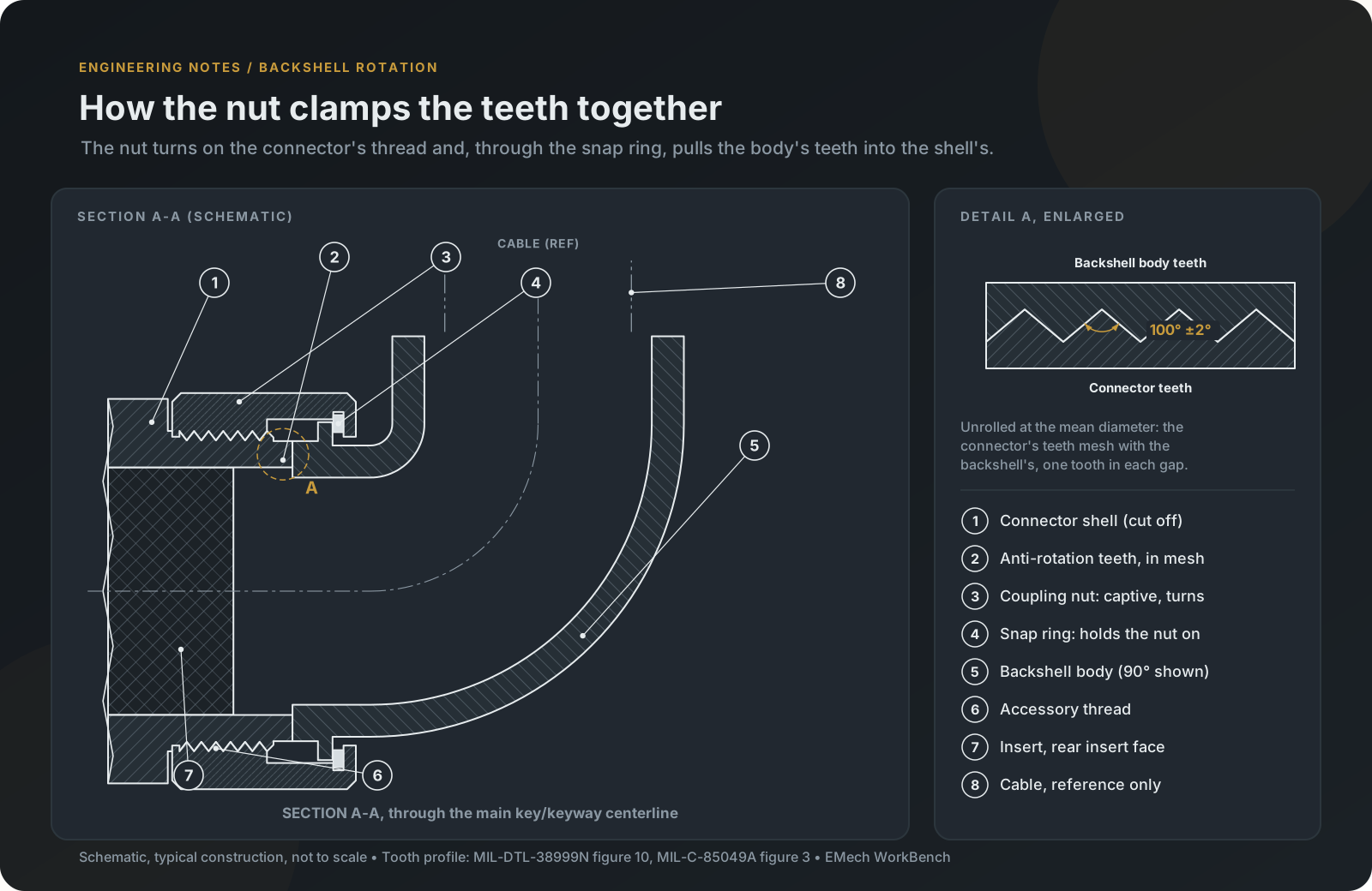
Most backshell couplings consist of two parts, the backshell body and the coupling nut. The M85049 sheets require the coupling nut to be captive on the body and free to rotate (for example M85049/16, p.4, and M85049/90, p.3). On a typical backshell, a snap ring in the nut bears on a flange on the body and keeps the nut from coming off. The nut threads onto the connector's accessory thread and, through that snap ring, pulls the body's teeth into the connector's teeth. The nut turns; the body doesn't. Once the teeth are in mesh, the body, and the cable exit with it, is locked at one tooth position.
The teeth are also the ground path
The anti-rotation teeth perform two functions. One is to lock the connector and its accessory together rotationally. The other is to provide a good grounding path from the backshell to the connector.
The accessory threads can and do provide a grounding path too, but it's not as good. As the threads are tightened, surface contamination builds up and gets compressed into the threads, which can raise the resistance. On top of that, almost any backshell with a rotating coupling nut (the ring with the threads that mate with the connector) uses a stainless steel internal snap ring to hold the coupling nut to the body of the backshell. The contact between the coupling nut and the snap ring, and between the snap ring and the body, is a very small surface area. And stainless steel, while conductive, is a poor conductor compared with the plated aluminum of a typical shell and backshell. This detail has caused many an inspector to reject a harness for poor grounding.
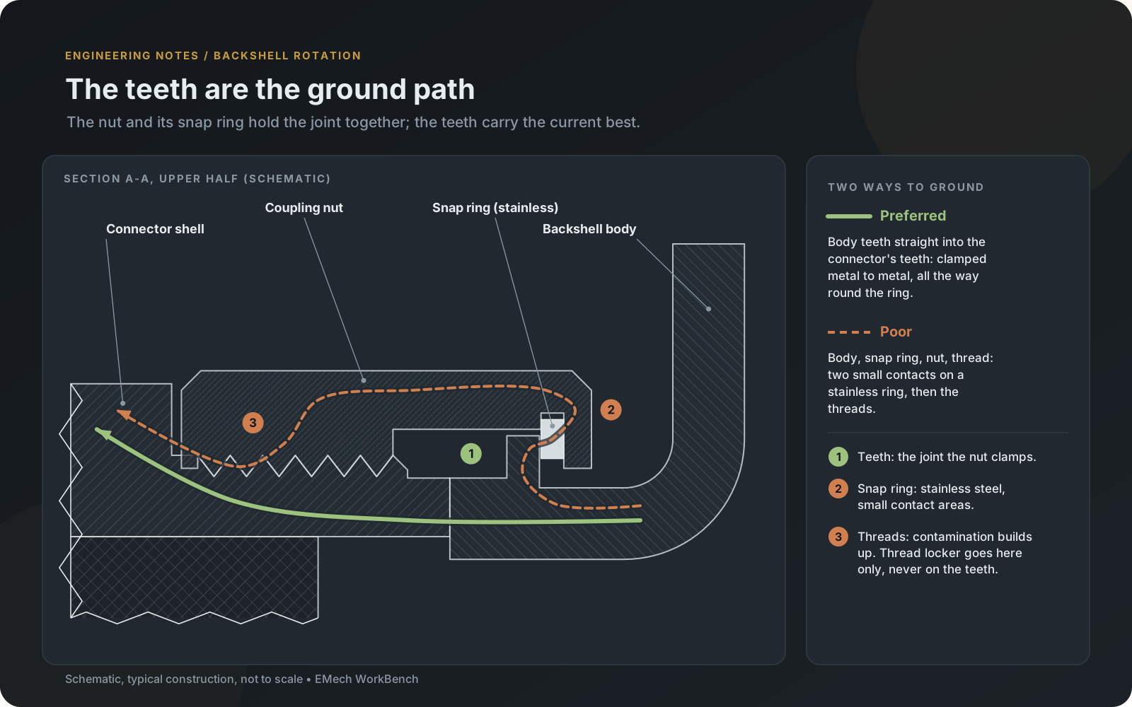
It comes up again when the system requirements call out severe vibration. The mechanical engineer will want to apply a chemical thread locker, and then the well-meaning EMI argument comes up: you can't use thread locker and maintain grounding. The correct answer is that you can use thread locker, if you have a good rapport with your technicians. The key is to apply it only to the interfacing threads and make sure none of it gets on the anti-rotation teeth, which are the preferred grounding path.
The tooth count sets the step
This is where the minimum angle comes from. With N teeth, a backshell has N positions, 360°/N apart, and nothing in between. The counts are the same in every series at the same accessory size: Series I, III and IV use the odd shell sizes, Series II the even ones, and Series IV has no size 9.
| Series I, III, IV shell size | Series II shell size | Teeth | Step between positions |
|---|---|---|---|
| 9 | 8 | 12 | 30° |
| 11 | 10 | 16 | 22.5° |
| 13 | 12 | 20 | 18° |
| 15 | 14 | 24 | 15° |
| 17 | 16 | 28 | 12.86° |
| 19 | 18 | 32 | 11.25° |
| 21 | 20 | 36 | 10° |
| 23 | 22 | 40 | 9° |
| 25 | 24 | 44 | 8.18° |
Tooth counts: MIL-DTL-38999N w/Amendment 2, figure 8 (p.115), figure 9 (p.119) and figure 10 (p.123); MIL-C-85049A table IX (p.41). The step is 360° divided by the count. The four tables follow, with the tooth count column outlined.
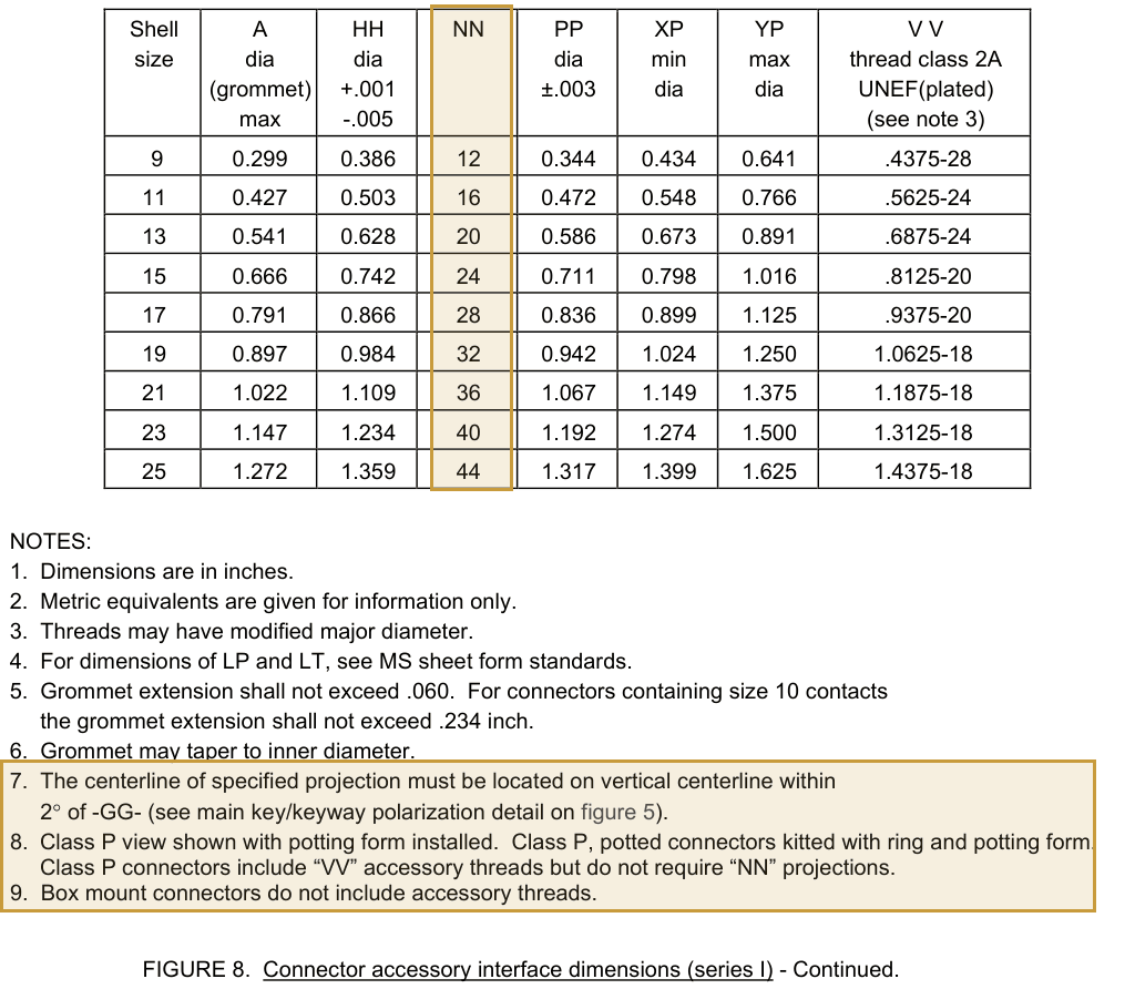
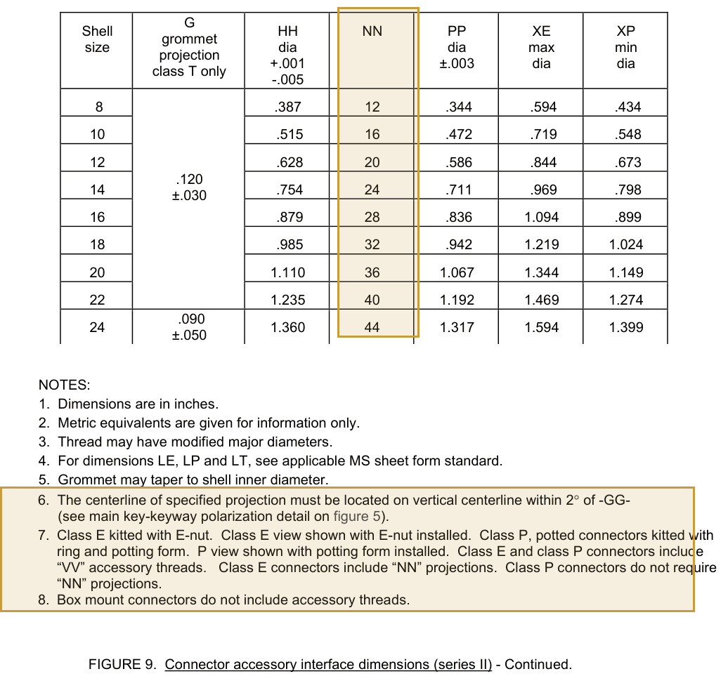
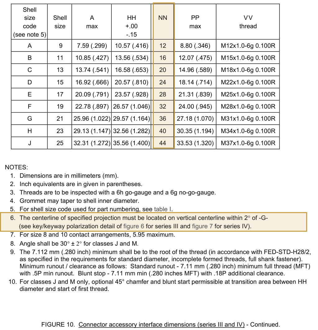
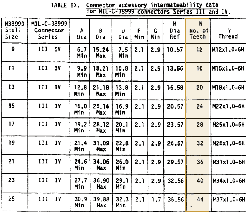
So on a size 9 shell, if the angle on your drawing lands between two teeth, the closest the shop can get is up to 15° away from it. No amount of care at the bench changes that.
With the coupling nut and snap ring cut away, you can see why there's nothing in between. As the backshell turns, its teeth ride up the connector's teeth until they sit crest on crest, then drop back into mesh one whole tooth further on.

A 45° elbow clocks the same way as a 90° elbow; only the bend of the exit is different. A straight backshell sends the cable straight out the back of the connector, so its clocking matters much less.
Where the steps start: the main key or keyway
The tooth ring can't sit just anywhere on the shell either. Each accessory interface figure puts one projection on the shell's vertical centerline, within 2° (note 6 of figure 10, note 7 of figure 8 and note 6 of figure 9, outlined in the tables above). What that centerline lines up with depends on the series.
Series III
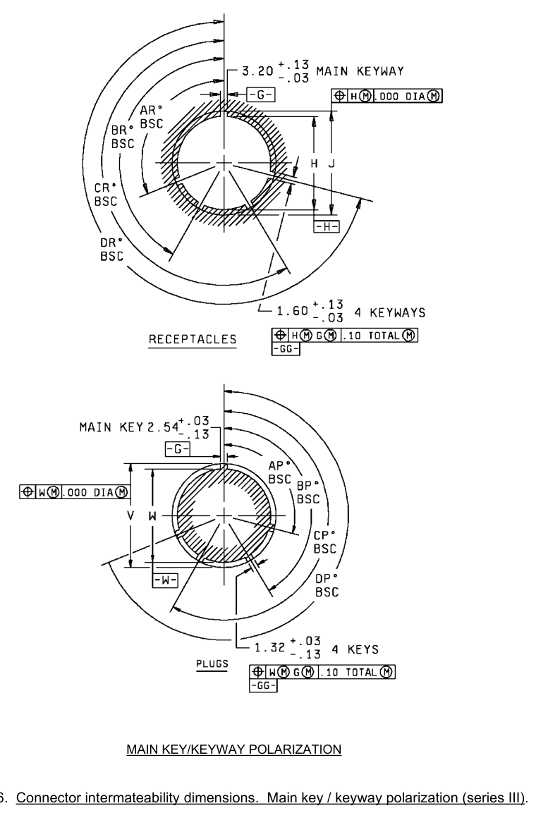
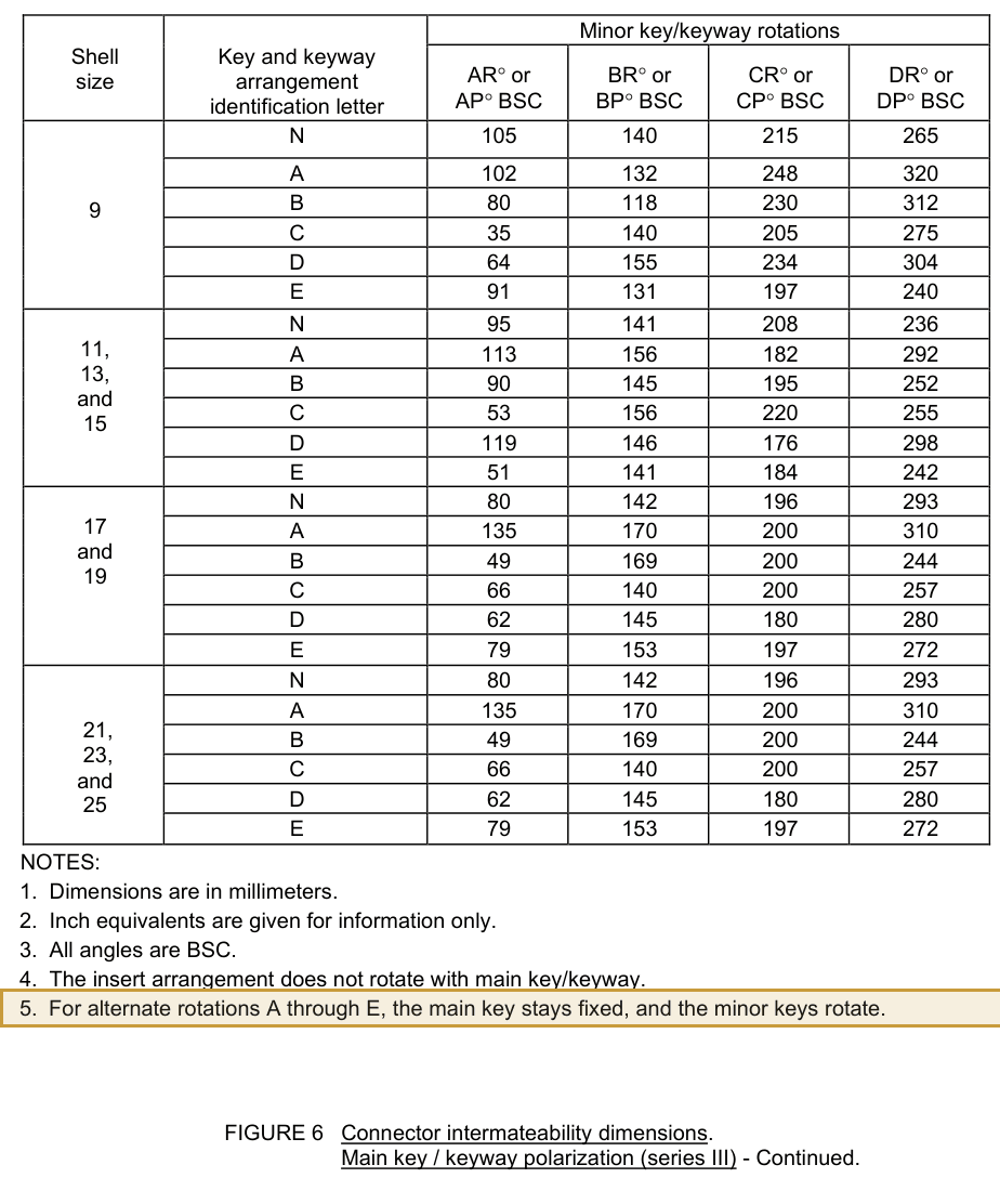
Figure 10 note 6 (p.123) puts the specified projection on the vertical centerline within 2° of datum -G-, which figure 6 (p.102) places on the main key (plugs) and main keyway (receptacles). Figure 6 note 5 (p.103) says that for the alternate positions A to E the main key stays fixed and the minor keys rotate. So in every polarization one tooth lines up with the main key or keyway, and the backshell can point straight over it, or any whole number of steps away from it.
Series IV
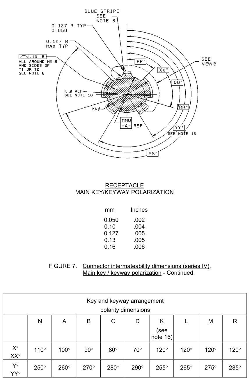
The same note 6 refers to the key/keyway detail of figure 7 instead. Series IV's polarization is defined differently, by the angles in figure 7 (pp.104-113), and this note doesn't work out where its main key/keyway sits for each letter. Check figure 7 for your polarization.
Series I and II
Figure 8 note 7 (p.115) and figure 9 note 6 (p.120) put the projection on the vertical centerline of figure 5. Figure 5 note 3 (p.101) makes that the insert arrangement's centerline, and says the insert and the 4 minor keyways don't rotate with the main key/keyway, which rotates to A, B, C or D for the alternates. So in the normal position, N, the main key/keyway is on the reference tooth. In A to D it's turned away from it, and the backshell positions no longer line up with it.
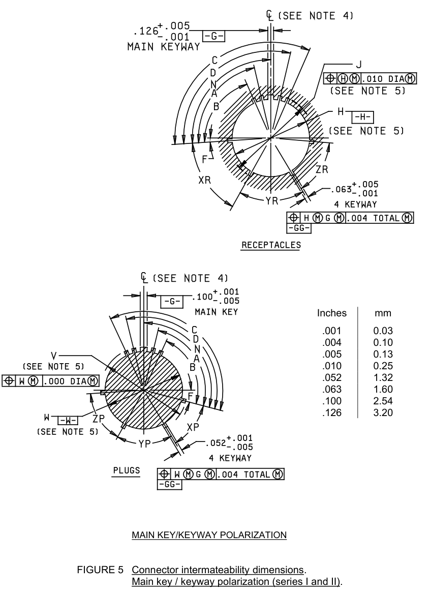
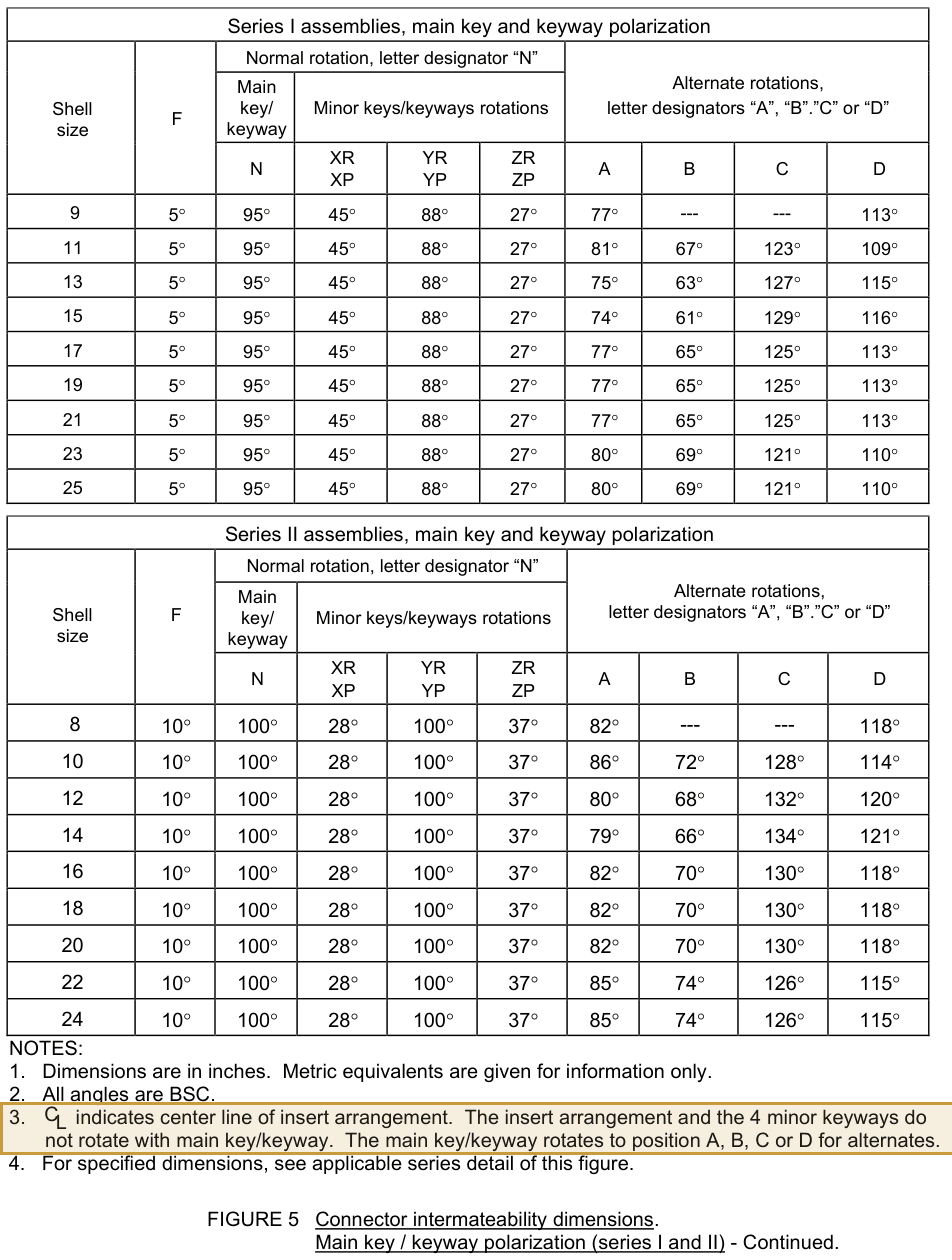
That ±2° is on the connector, so a real assembly can sit up to that much off the nominal angles in this note. It's one more reason not to dimension a clocking angle tighter than the hardware can hold.
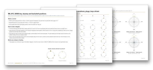
The key, keyway and backshell positions PDF draws every shell size and polarization letter for Series I, II and III, plugs and receptacles, the same way the builders draw them, so you can see the main key/keyway and minor keys side by side. Its last two pages are the builders' backshell orientation images: every position the teeth allow, for every shell size of all four series.
For Series I and II, the table below gives how far the main key/keyway sits from the reference tooth. The offsets are worked out from the angles in figure 5 (p.101, above), the same way the builder's keyway diagram draws them. A and D are mirror images of each other, and so are B and C.
| Series I shell size | Series II shell size | Teeth | A or D: main key offset | B or C: main key offset |
|---|---|---|---|---|
| 9 | 8 | 12 | 18° | not offered |
| 11 | 10 | 16 | 14° | 28° |
| 13 | 12 | 20 | 20° | 32° |
| 15 | 14 | 24 | 21° | 34° |
| 17 | 16 | 28 | 18° | 30° |
| 19 | 18 | 32 | 18° | 30° |
| 21 | 20 | 36 | 18° | 30° |
| 23 | 22 | 40 | 15° | 26° |
| 25 | 24 | 44 | 15° | 26° |
Figure 5 prints no B or C position for Series I size 9 and Series II size 8. In position N the offset is 0° at every size.
Why it matters in a harness and on a panel
The exit direction decides where the bundle goes first. An elbow aimed one step off can point the cable at a bracket, a neighboring connector or a clamp location instead of the clear path.
Any miss between the reachable position and the route the harness needs turns into a bend right behind the backshell, where the bundle is stiffest. On the smallest shells that can be as much as 15°.
On a panel with several connectors, elbows clocked toward each other can clash, or block the coupling ring of the next connector, so plan each elbow's direction together with its neighbors. Leave room for hands, too. The coupling ring of a plug has to be gripped to mate and unmate it, and a shield band or boot has to be installed behind the backshell. An elbow clocked into the wrong quadrant can leave no room for a hand or a tool.
When a plug is mated, its main key sits in the receptacle's main keyway. Both backshells are then referenced to the same keyway, so the receptacle's mounted orientation sets the possible exit directions on both sides of the panel.
On the drawing, give the exit direction as an angle from the main key or keyway, say which end of the connector the view is from and which way the angle runs, and use one of the reachable values. A plug and a receptacle seen from their own mating faces are mirror images of each other, so the same angle can be clockwise on one and counterclockwise on the other. Then put a tolerance on it that the hardware can actually hold. That's the lesson from the inspection reject at the top of this note.