An accessory must match the connector interface and the installation. Start with the connector's specification, series, shell size, rear accessory thread, finish, and the cable or harness requirements. Then verify the accessory's detail sheet, dimensions, materials, and approved configuration.
M85049 covers a family of electrical connector accessories. The exact part-number pattern depends on the accessory type and its detail sheet; there is no single suffix format that applies to every accessory. For example, this /16 strain-relief pattern is M85049/16S11W:
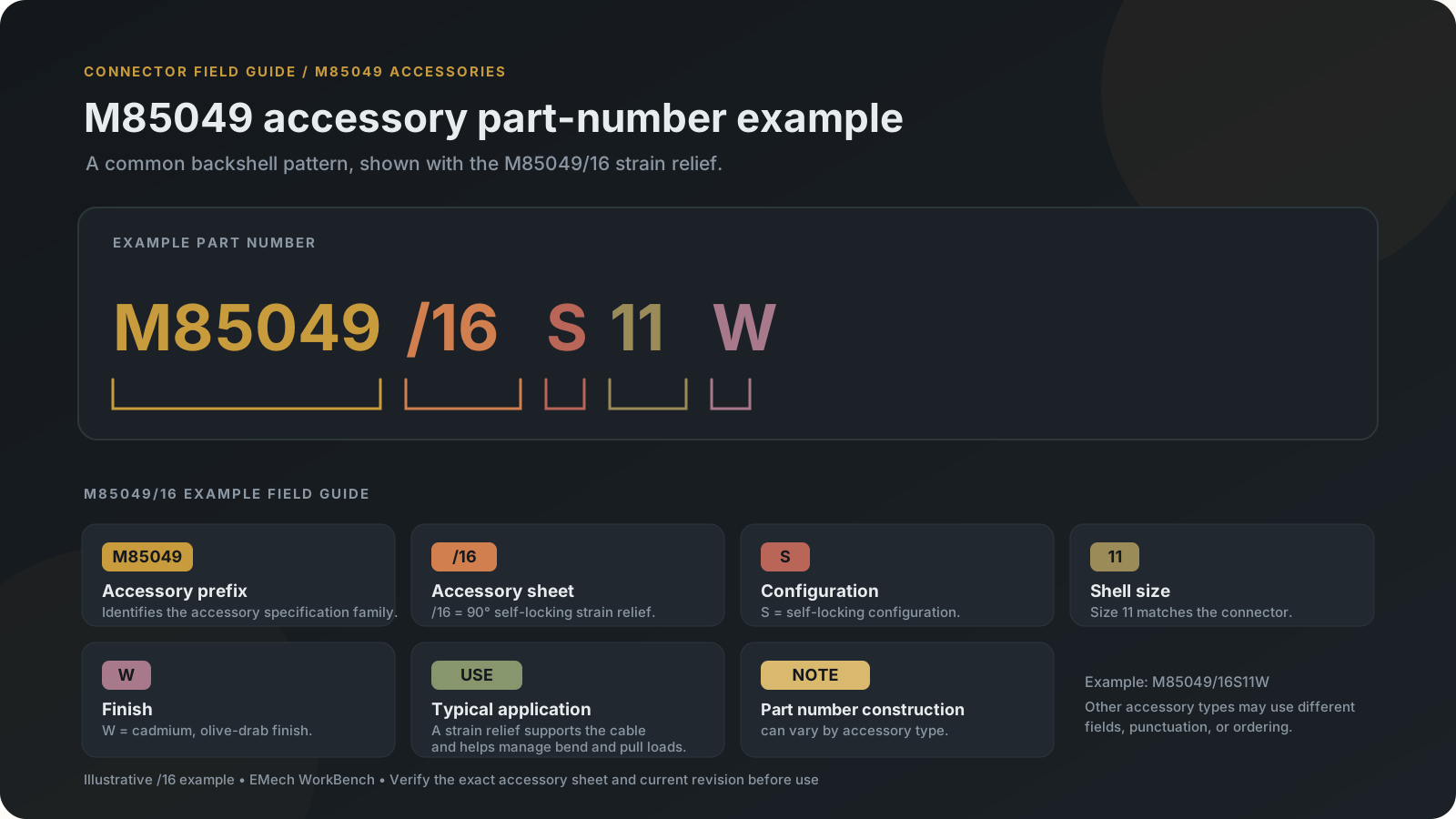
In this example, /16 identifies the accessory sheet, S selects the self-locking configuration, 11 is the shell size, and W is the finish code. Other sheets can use different fields, separators, and order. Always decode a part number against its own current detail sheet.
Backshell and connector-side accessories
Backshells attach to the rear of a connector and provide a mechanical or electrical interface for cable routing, strain control, environmental protection, or shield termination. The correct style depends on the connector's accessory thread, shell size, cable bundle, routing direction, sealing requirements, and shielding design.
Strain-relief backshells — /16, /38, /39, /91, /92
Use strain relief when the cable bundle needs support at the connector exit to reduce pull and bending loads transferred into the connector and terminations. Choose among the represented sheets based on cable direction, locking configuration, and specified material:
| Sheet | Style | Choose it when | Check |
|---|---|---|---|
/16 | 90-degree, self-locking | The cable needs to turn 90 degrees at the connector and the installation calls for self-locking coupling. | The strain-relief arm is secured with the tie, twine, or lacing methods named on the sheet; a grounding-lug configuration is also represented. Check the entry maximum and contact-size exclusions. |
/38 | Straight, self-locking or non-self-locking | The cable exits straight and either configuration is required. | The sheet gives a wire-bundle accommodation range and multiple finishes. The non-self-locking PIN uses a dash in the configuration position. |
/39 | 90-degree, self-locking or non-self-locking | The cable exits at a right angle and either configuration is appropriate. | The non-self-locking configuration position is left blank, unlike /38; follow the exact sheet syntax. |
/91 | Straight, composite, self-locking | The design specifies this composite, straight-exit style. | The cable-entry diameter is given with the saddle bars closed against the clamp ears; compare the bundle against that measurement condition. |
/92 | 90-degree, composite, self-locking | The same composite style is required but the cable must exit at 90 degrees. | Apply the sheet's cable-entry measurement condition and check compatibility for the exact connector. |
The builder's data flags /16, /38, /39, /91, and /92 as unsuitable for connectors using size 8, 4, or 0 contacts. Check that constraint along with shell-size-specific cable entry before selecting one.
Backshells with cable clamps — /18, /19, /21
Use one of these when the cable needs a backshell-mounted clamp and a straight exit. Choose the sheet according to the environmental and shielding features required by the design:
| Sheet | Style | Choose it when | Check |
|---|---|---|---|
/18 | Environmental, RFI/EMI | The installation calls for the environmental style together with the RFI/EMI provision. | Select a clamp size for the measured cable diameter and a length that fits the assembly envelope. |
/19 | Non-environmental, RFI/EMI | The RFI/EMI style is needed but the environmental version is not required. | Its cable-clamp ranges differ from /18; select from /19's own sizing table. |
/21 | Non-environmental, no RFI/EMI designation | A basic straight cable-clamp backshell is enough. | Check the finish and clamp range in its own sheet. |
All three provide length choices in the current dataset. Compare the selected length, clamp range, and connector/cable clearances against the actual installation rather than treating the category labels as a complete environmental or EMC qualification.
Shield-termination backshells — /20, /78, /79, /85, /86, /87, /88, /89, /90
Use these styles when the cable shield must terminate at the connector-side backshell as part of the design's shielding path. The useful choice depends on the shield termination method, sealing requirement, and cable direction:
| Sheet | Termination | Exit | For | Choose it when | Check |
|---|---|---|---|---|---|
/20 | Shield crimp ring, RFI/EMI | Straight | The specified termination uses a crimp ring rather than the cone or band method. | The sheet identifies the ring and crimp tooling; verify the ring, tool, and shield preparation together. | |
/78 | Single shield, single cone, environmental | 45° | An environmental backshell is required and a 45-degree exit suits the cable route. | ||
/79 | Single shield, single cone, environmental | 90° | The same termination is needed with a 90-degree exit. | The source sheet says it does not fit MIL-C-38999 Series IV jam-nut receptacles; the builder excludes that combination. | |
/85 | Shield band, heat-shrink boot interface | Straight | 38999 Series I/II | The cable can run directly behind the connector and the design calls for a band plus a boot. | Specified for Category 3B; verify the connector interface and the selected band and boot. |
/86 | Shield band | 45° | 38999 Series I/II | A straight backshell would take too much axial room and the harness must route around nearby structure. | Check the cable's bend radius and installation clearance. |
/87 | Shield band | 90° | 38999 Series I/II | A compact layout requires the harness to turn at the connector. | Confirm cable-entry limits, bend radius, and clearance; the backshell angle does not define the cable's allowable bend radius. |
/88 | Shield band | Straight | 38999 Series III/IV | The cable runs directly back and the shield is attached with a separate band. | Size the cable entry and band to the specific backshell and cable construction. |
/89 | Shield band | 45° | 38999 Series III/IV | The harness needs to turn away from the connector while keeping the band attachment. | |
/90 | Shield band | 90° | 38999 Series III/IV | The cable must turn at a right angle near the connector. | Check bend radius and surrounding clearance before committing to the layout. |
For /88–/90, pair the backshell with a compatible /128 shield band and its installation tool. Do not interchange the crimp-ring, cone, and band approaches without checking the applicable detail sheets and the system shielding design.
The /85–/87 family is for MIL-DTL-38999 Series I/II; /88–/90 is for Series III/IV. Within each family, the three sheet numbers map to straight, 45-degree, and 90-degree cable exits. Similar termination methods do not make the series interfaces interchangeable. The /85 specification also identifies Category 3B and a heat-shrink boot interface. Check the applicable current detail sheet and connector compatibility before selection. SAE AS85049/85.
Shrink-boot adapter — /69
Choose the /69 adapter when the design calls for a heat-shrink boot and needs the corresponding connector-side seat/interface. Confirm the adapter's actual diameter and groove, the boot's recovered and supplied dimensions, and the compatibility statements on both detail sheets. The /69 sheet historically names M85049/68 boots; that older boot specification has been canceled and superseded. Do not assume every boot fits every adapter solely because the family number is M85049.
Cable protection and harness accessories
| Sheet | Accessory | Use it when | Choose and check |
|---|---|---|---|
/140 | Heat-shrink boot, straight | The design needs a protected transition from a compatible backshell to the wire bundle. | Style, size, material, adhesive, drain, and port options affect fit and use. Match the adapter-end size and the cable-end diameter to the actual assembly. |
/141 | Heat-shrink boot, 90-degree | The same protected transition is needed with a 90-degree turn. | Same as /140. |
/142 | Heat-shrink transition: tee, wye, or one-to-three | A cable branch or breakout needs to be joined and protected. | Not selected by connector shell size. Choose the style and size from the cable diameters, branch geometry, material, adhesive, and installation space. |
/128 | Shield band | A cable shield must be clamped onto a compatible shield-band backshell, including the /88–/90 styles. | The band and installation tool must match the backshell surface and the cable/shield construction. |
The site's boot dimensions, ordering options, band sizes and tooling information come from secondary sources, because the current SAE sheets were not available when the data was entered. Verify the exact part against the current SAE-AS85049 sheet and the product's own documentation.
Contact-cavity accessories
| Sheet | Accessory | Sizes in the data | Use it when | Check |
|---|---|---|---|---|
/80 | Dummy contact | 12 and 8 | The connector instructions call for a dummy in an unwired cavity in place of an unused contact and sealing plug. | Confirm the connector family, cavity size, sealing requirement, and insertion/removal tool from the sheet before assembly. |
/81 | Seal plug | 10 | An unused size 10 contact cavity must be closed. | The sheet's tool table lists tools for sizes 12 and 8, not size 10; verify the installation tool and procedure with the current controlling documentation. |
Protective covers and dust caps
Protective covers and dust caps shield an unmated connector interface from handling damage and contamination during storage, transport, or maintenance.
| Cover | For | In the builders |
|---|---|---|
| M85049/138 plastic dust cap | MIL-DTL-38999 Series III/IV | Listed, but its part numbers are not built |
| MS3180 plug cover | MIL-DTL-26482 Series 2 | Built in the Series 2 Accessories panel |
| MS3181 receptacle cover | MIL-DTL-26482 Series 2 | Built in the Series 2 Accessories panel |
Check whether a cover is qualified for the exact connector interface; covers are not substitutes for mating connectors or cavity seal plugs.
Choosing the right accessory
- Identify the connector's exact standard, series, shell style, shell size, and rear accessory interface.
- Define the actual need: strain support, cable clamping, environmental protection, shield termination, boot transition, cavity sealing, or protection while unmated.
- Check cable bundle diameter, exit angle, material/finish, environmental conditions, shielding method, and installation space.
- Build or decode the accessory part number using the accessory's own sheet format.
- Verify dimensions, compatibility, installation tooling, current revision, and supplier availability before release or purchase.
The EMech WorkBench builders narrow the options for the connector series and accessory data they currently support: choose the connector first, and the accessory choices follow from it. A builder may disable a choice when its data identifies an incompatibility, and it may omit options that are not in its data. An option missing from the tool may be a coverage gap, not a statement that the accessory is invalid or unavailable. An option that appears in the tool does not replace checking the current specification and product documentation.
Current data scope
| Builder | Accessories offered |
|---|---|
| MIL-DTL-38999 Series III and IV | A subset of M85049: strain reliefs, cable-clamp backshells, shield-termination backshells, a shrink-boot adapter, heat-shrink boots and transitions, shield bands, dummy contacts, and seal plugs. Several SAE-only sheets are listed without full part-number building, and some families, including the /138 dust cap, are not selectable. |
| MIL-DTL-38999 Series I and II | One sheet, /32, a 90-degree shield-termination backshell. The band-termination sheets /85–/87 described above are not built in any builder. |
| MIL-DTL-26482 Series 2 | Its own M85049 backshell data and the MS3180 and MS3181 protective covers |
| MIL-DTL-5015 and MIL-DTL-83723 Series III | The M85049 backshells for their crimp connectors, plus protective covers and a seal plug |
Use the specific connector builder's visible coverage notes.
Many older MIL-C-85049 sheets were canceled and superseded by SAE-AS85049. The site's data cites the source edition and warns where secondary sources were used. Confirm the current SAE sheet and supplier documentation for the exact part.
The site does not provide a complete M85049 catalog, a universal cross-series fit guarantee, or live supplier inventory, price, or lead time. An absent accessory result may reflect data coverage rather than nonexistence. Confirm the exact part and its availability with the supplier.