Use the EMech WorkBench builder to assemble or decode supported MIL-DTL-38999 connector part numbers. Choose a series and shell style, then work through the applicable part-number fields. When the selected combination is supported by the current data, the tool shows the resulting part number and related information such as contacts, mating connectors, or accessories.
The builder covers general-purpose and hermetic shell styles in Series I, II, III, and IV. The series differ in coupling style and in the part-number fields they use, so start with the series specified by your design or interface requirement. If you are decoding an existing part number, enter it on the matching series page.
Choose a series
- Series I: bayonet coupling, scoop-proof. The current builder includes a subset of Series I shell styles; check the page's coverage note before treating a missing style as invalid.
- Series II: bayonet coupling, low silhouette, non-scoop-proof. The current builder includes a subset of Series II shell styles.
- Series III: triple-start threaded coupling, scoop-proof.
- Series IV: breech coupling, scoop-proof.
Open the MIL-DTL-38999 connector builders to select a series. The series pages identify their supported shell styles, input fields, and data limitations.
How to build or decode a part number
- Select the builder for the correct series.
- To decode, enter the part number as marked and use the decoder. Review the fields the tool recognizes.
- To build, select the shell style and complete the available fields in order. Options can depend on earlier selections.
- Review the assembled part number and its breakdown. Use the mating and accessory sections only for the combinations and data shown.
- Verify the result against the current controlling specification and applicable slash sheets before using it on a released design or purchase order.
The builder is a reference aid. A field or option that is absent from the current data set should not be assumed to be prohibited by the specification.
What the builder can show
Depending on the series and selected configuration, the tool can show insert arrangements and diagrams, contact information, candidate mating connectors, and supported M85049 accessory information. The available details differ by series. A blank result means the selected combination is outside the current data scope; it is not proof that no compatible part exists.
Data sources and limitations
The current 38999 data is based on MIL-DTL-38999N with Amendment 2, its supplement where noted, and MIL-STD-1560 arrangement data. The builder pages identify their inputs and call out series-specific review items. Series I and II currently include only subsets of their listed shell styles. Series III and IV also have documented scope limits; Series IV shell-style coverage has not been cross-verified against Supplement 1. Review the applicable page's disclaimer and coverage notes before relying on a result.
Series III part-number fields and options
This section explains the Series III format only. Series I and II use a different field order and different rules; use their own builder pages for those formats.
Example, with spaces added to make the fields easier to see:
D38999 /24 W J 35 P N
The spaces are visual separators. In a part number, the fields are normally written together as D38999/24WJ35PN.
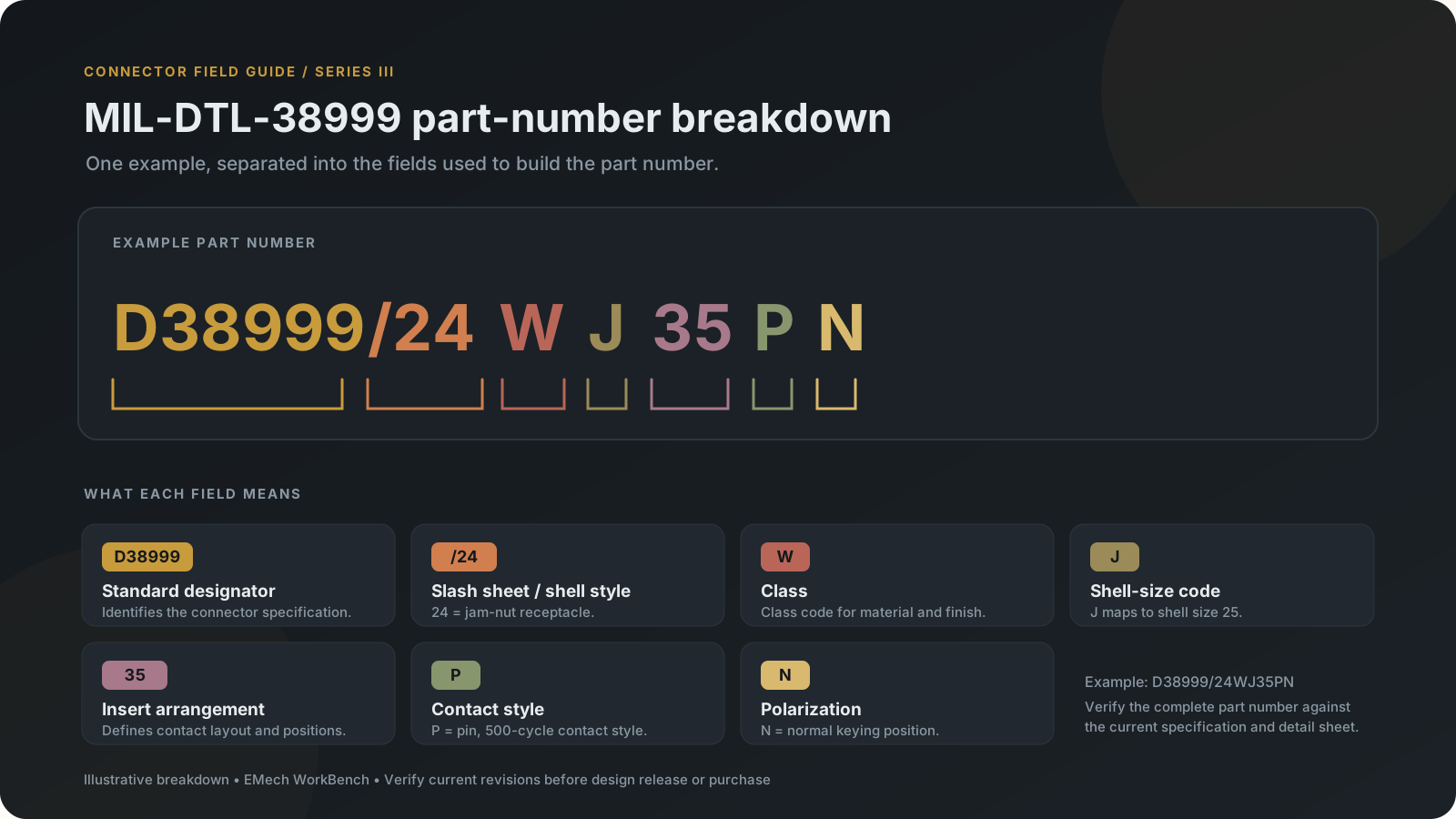
| Field | Example | Meaning and options in the current Series III builder |
|---|---|---|
| Specification designator | D38999 | Identifies the MIL-DTL-38999 part-number family. |
| Slash sheet / shell style | /24 | The slash-sheet number identifies the connector style. The builder currently includes /20 wall-mount receptacle, /24 jam-nut receptacle, /26 straight plug, and hermetic /21 box-mount, /23 jam-nut, /25 solder-mount, and /27 weld-mount receptacles. |
| Class | W | Identifies the class, including material and finish requirements. The current general-purpose subset offers C, F, G, K, T, and W; hermetic classes offered are N and Y. See the table below. |
| Shell-size code | J | A letter code from the Series III/IV shell-size table. J means shell size 25; the full mapping is below. |
| Insert arrangement | 35 | Identifies the contact layout. Options depend on shell size and are drawn from the builder's MIL-STD-1560 arrangement data. The selected arrangement determines contact positions and sizes shown by the tool. |
| Contact style | P | Identifies contact gender and style. The general-purpose builder offers the pin/socket styles below; hermetic styles are fixed-contact pin terminations in the current dataset. |
| Polarization | N | Identifies the key/keyway position. Series III writes a polarization letter explicitly, including N for normal. The current data offers N, A, B, C, D, and E. |
Shell-style codes in the current builder
| Code | Shell style |
|---|---|
/20 | Wall-mount receptacle |
/24 | Jam-nut receptacle |
/26 | Straight plug |
/21 | Hermetic box-mount receptacle |
/23 | Hermetic jam-nut receptacle |
/25 | Hermetic solder-mount receptacle |
/27 | Hermetic weld-mount receptacle |
These are the shell styles represented by the current Series III tool. Lanyard-release styles, filtered connectors, and NATC variants are outside its current data scope. The shell-style list also has a documented Supplement 1 cross-reference limitation; see the Series III builder's coverage disclaimer.
Class codes currently offered
| Class | Current dataset description |
|---|---|
C | Aluminum, anodic nonconductive finish |
F | Aluminum, electroless nickel conductive finish |
G | Aluminum, electroless nickel conductive finish, space grade |
K | Stainless steel, passivated conductive/firewall class |
T | Aluminum, nickel-fluorocarbon polymer conductive finish |
W | Aluminum, cadmium olive-drab conductive finish |
N | Hermetic stainless steel, electrodeposited nickel conductive finish |
Y | Hermetic stainless steel, passivated conductive finish |
The base specification's class table has additional designators, but its applicability columns require further manual verification. This builder intentionally offers a practical verified subset; the list above is not the full class list in the specification.
Shell-size code mapping
| Code | Shell size | Code | Shell size | Code | Shell size |
|---|---|---|---|---|---|
A | 9 | B | 11 | C | 13 |
D | 15 | E | 17 | F | 19 |
G | 21 | H | 23 | J | 25 |
The letter is the part-number code; it is not the shell-size number itself. For example, J in the example means shell size 25.
General-purpose contact-style codes
| Code | Meaning in the current dataset |
|---|---|
P | Pin, 500-cycle |
S | Socket, 500-cycle |
H | Pin, 1,500-cycle contact |
J | Socket, 1,500-cycle contact |
R | Pin, rhodium-plated contact |
M | Socket, rhodium-plated contact |
G | Pin, heavy-gold-plated contact |
U | Socket, heavy-gold-plated contact |
The 1,500-cycle rating applies to the H/J contacts; connector-level durability can have separate limits. For R/M and G/U, the current tool identifies the applicable contact slash sheet but does not have all contact dash numbers. Check the governing contact specification before ordering.
Hermetic contact-style codes
The current dataset offers P for pin solder-cup termination, X for pin eyelet termination, and C for pin feed-through termination. These are fixed contacts. Socket-side hermetic codes are omitted while their applicability to the offered hermetic classes remains unresolved in the builder's source review.
Polarization codes
| Code | Position |
|---|---|
N | Normal |
A | Alternate A |
B | Alternate B |
C | Alternate C |
D | Alternate D |
E | Alternate E |
All six letters are represented for Series III shell sizes 9–25 in the current data. The letter describes keying position; verify the physical interface and applicable drawing for the actual assembly.
Reading the example
D38999/24WJ35PN reads as a MIL-DTL-38999 Series III, /24 jam-nut receptacle, class W, shell size 25 (J), insert arrangement 35, pin contact style P, and normal polarization N. This decodes the fields represented by the builder; it does not by itself establish that the part is appropriate for a particular application or that it is currently available from a supplier.
Specifications and adopted standards can change. Confirm the current revision, the applicable slash sheet, and manufacturer requirements for the exact part before design release or procurement.
Supplier availability: This page does not provide live supplier pricing or lead time. Check with the supplier for current stock, price, and delivery information.